Imagine designing a massive spillway, only to discover that the water behaves completely differently once construction is finished. Unexpected turbulence, excessive pressure, or unstable flow patterns could turn an expensive engineering project into an even bigger problem.
That’s exactly why accurate hydraulic modeling matters.
Today, engineers don’t have to rely entirely on physical experiments or simplified mathematical equations to understand complex water movements.
Computational Fluid Dynamics (CFD) allows them to explore how fluids behave inside pipelines, rivers, pumping stations, dams, and other hydraulic structures before making major design decisions.
But there’s a catch. Not every simulation delivers reliable results, especially when complicated geometries and turbulent flow conditions are involved.
This is where optimizing hydraulic simulations using high-resolution CFD models becomes particularly valuable.
By combining detailed computational meshes, appropriate turbulence models, and efficient numerical methods, engineers can capture important flow characteristics while controlling simulation costs.
In this guide, we’ll explore how high-resolution CFD works, why optimization matters, and which practical techniques can make hydraulic simulations more accurate, efficient, and useful for real-world engineering projects.
1. Why High-Resolution CFD Matters in Hydraulic Engineering
Hydraulic engineering has always involved balancing mathematical predictions with unpredictable real-world conditions. Water may look simple, but its behavior becomes surprisingly complicated around obstacles, narrow channels, sharp bends, and sudden elevation changes.
Traditional hydraulic calculations often rely on assumptions about flow uniformity, average velocity, and energy losses. These approaches remain extremely useful, although they cannot always describe detailed three-dimensional flow structures.
High-resolution CFD provides a more detailed perspective.
Understanding High-Resolution Flow Modeling
Computational Fluid Dynamics uses numerical techniques to solve equations governing fluid motion, particularly the Navier–Stokes equations.
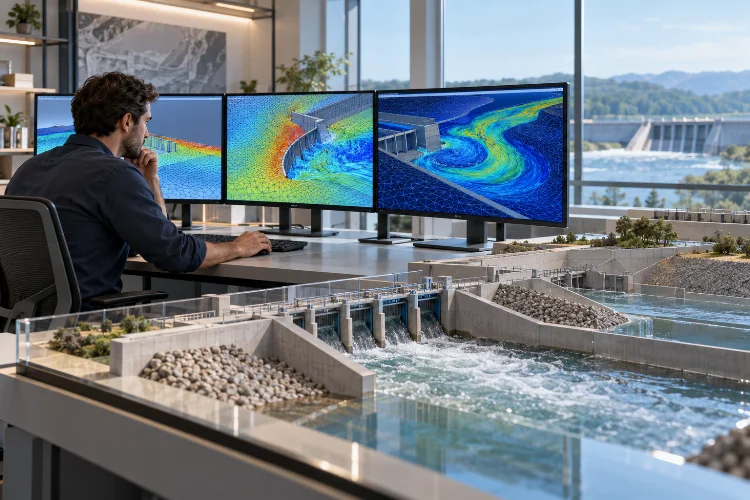
Instead of treating an entire river section or hydraulic structure as a single calculation, CFD divides the computational domain into numerous smaller cells. Within these cells, numerical algorithms estimate variables such as velocity, pressure, and turbulence quantities.
The smaller these cells become, the more spatial detail the simulation can potentially capture.
For example, consider water flowing around a bridge pier. A simplified hydraulic model might estimate average velocity and water levels, while a three-dimensional CFD simulation can reveal localized acceleration, recirculation zones, and complicated pressure distributions.
These details are particularly important when evaluating hydraulic loading and identifying areas susceptible to erosion.
The Difference Between Resolution and Accuracy
Here’s something worth remembering: a finer computational mesh doesn’t automatically produce a more accurate simulation.
Accuracy also depends on boundary conditions, geometric representation, turbulence modeling, numerical schemes, and the quality of available measurements.
A simulation containing millions of cells might still generate misleading results if its upstream flow conditions are incorrect.
That’s why optimization should focus on improving the overall modeling process, not simply increasing mesh density.
The goal is to capture physically meaningful details without introducing unnecessary computational complexity.
2. Building a Reliable Foundation for CFD Simulations
Before increasing simulation resolution, engineers need to establish a reliable physical and numerical model.
Skipping this preparation can create problems that additional computing power simply cannot fix.
Define the Engineering Objective First
Every successful hydraulic simulation begins with a clear question.
Are you investigating pressure losses in a pipeline? Evaluating spillway performance? Predicting water surface elevations? Or studying turbulent circulation near a pumping station?
These objectives influence the entire modeling strategy.
For instance, engineers analyzing head losses through a pipe fitting may focus on pressure differences and internal velocity distributions. Meanwhile, a spillway study may require detailed free-surface tracking and transient flow behavior.
Trying to capture every possible flow characteristic often makes simulations unnecessarily complicated.
Instead, identify the quantities that directly support your engineering decision.
Prepare Accurate Geometry and Boundary Conditions
Geometry plays a major role in hydraulic performance.
Small design features, including sudden contractions, channel transitions, and sharp structural edges, can create significant local changes in water velocity and pressure.
However, modeling every tiny surface imperfection isn’t always practical.
Engineers should preserve geometrical features that influence important flow behavior while simplifying details that have negligible hydraulic effects.
Boundary conditions deserve equal attention.
Inlet discharge, downstream water level, wall roughness, pressure, and initial flow conditions must represent the intended operating scenario.
Suppose a pumping station normally operates at a discharge of 12 cubic meters per second. Using that value for one design scenario makes sense, but additional simulations may be needed to examine maximum operating conditions and unusual flow patterns.
The key is making sure input data reflects the actual engineering problem.
A high-resolution mesh cannot compensate for inaccurate assumptions about how water enters or leaves the system.
3. Optimizing Mesh Resolution Without Wasting Computing Power
Mesh generation is arguably one of the most important steps in high-resolution hydraulic modeling.
It also presents one of the biggest opportunities for optimization.
Creating an extremely fine mesh across the entire computational domain might sound like the safest approach. Unfortunately, that strategy can dramatically increase processing time, memory requirements, and simulation costs.
A smarter solution is selective refinement.
Focus Resolution on Critical Flow Regions
Not every part of a hydraulic system requires the same computational detail.
In a relatively straight river section, velocity changes may occur gradually. Around bridge piers, gates, sharp bends, or spillway transitions, flow gradients can become much stronger.
These complex regions benefit from additional mesh resolution.
Local mesh refinement allows engineers to concentrate smaller computational cells around important hydraulic features while maintaining larger cells elsewhere.
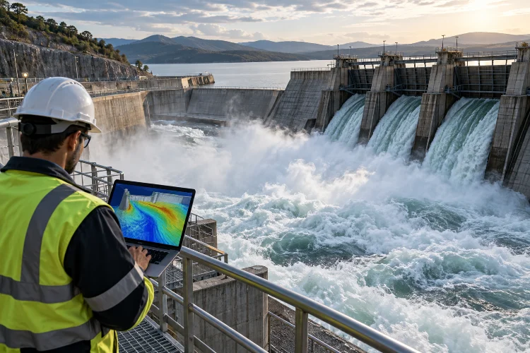
For example, a spillway simulation may use relatively coarse cells in the upstream reservoir and progressively finer cells around the crest, high-velocity chute, and energy dissipation basin.
This approach can provide detailed local predictions without making the entire model unnecessarily expensive.
Understand the Computational Cost of Refinement
Consider a three-dimensional simulation using approximately one million computational cells.
If the cell dimensions are halved throughout the entire domain, the number of cells could increase to roughly eight million.
For transient simulations, smaller cells may also require shorter time steps to maintain numerical stability.
Under simple Courant-number constraints, halving both spatial dimensions and time-step size could increase the overall computational workload by approximately sixteen times.
Actual performance depends on solver behavior, parallel efficiency, and other numerical factors, but the example highlights an important point.
More resolution comes with a price.
Mesh Quality Matters as Much as Cell Count
Engineers should also evaluate mesh quality indicators, including skewness, non-orthogonality, aspect ratio, and cell-size transitions.
Poorly shaped cells can reduce numerical accuracy and sometimes cause unstable solutions.
A carefully structured mesh can often perform better than a considerably larger mesh containing distorted cells.
Modern CFD tools provide automated quality checks to help identify these problems before simulation begins.
The goal is to create a mesh that can accomodate complicated hydraulic geometries while preserving reliable numerical behavior.
4. Choosing Turbulence and Free-Surface Models
Water flowing through real hydraulic systems is frequently turbulent.
Instead of moving smoothly in parallel layers, the fluid develops fluctuating velocity patterns, swirling structures, and complex mixing processes.
These characteristics influence pressure losses, energy dissipation, sediment movement, and structural loading.
Choosing an appropriate turbulence model is therefore essential.
Comparing RANS, LES, and Hybrid Approaches
Reynolds-Averaged Navier–Stokes (RANS) models are widely used because they approximate the effects of turbulence without explicitly resolving every turbulent motion.
Models such as k–ε and k–ω SST offer practical options for many engineering applications.
The standard k–ε model can be useful for relatively established turbulent flows, while k–ω SST is often considered when adverse pressure gradients and flow separation matter.
However, neither model is universally superior.
Large Eddy Simulation (LES) resolves larger turbulent structures while modeling smaller-scale motions. This can provide detailed information about unsteady vortices and mixing behavior, although computational requirements are typically much higher.
Hybrid RANS – LES approaches attempt to combine the efficiency of RANS with higher-resolution turbulence treatment in selected regions.
For everyday engineering studies, RANS may offer a reasonable starting point. LES becomes particularly interesting when transient turbulent structures are central to the problem.
Modeling Water – Air Interactions
Some hydraulic simulations involve both water and air.
Examples include dam-break flows, spillway overtopping, hydraulic jumps, and rapidly changing free surfaces.
The Volume of Fluid (VOF) method is commonly used to track the interface between immiscible fluids.
Rather than defining the water surface as a permanently fixed boundary, VOF tracks the distribution of fluid phases within computational cells.
This makes it useful for simulating moving water surfaces, wave formation, and certain water–air interactions.
However, fine-scale bubble entrainment and aeration may require additional modeling assumptions, validation, or more sophisticated multiphase methods.
A model that accurately captures a free surface does not automatically predict every detail of air entrainment.
5. Improving Numerical Stability and Simulation Efficiency
Even with excellent geometry and mesh quality, a CFD simulation can struggle if its numerical settings are poorly configured.
Solvers must balance accuracy, stability, and computational efficiency.
Getting this balance right can make a substantial difference in project delivery.
Select Appropriate Time Steps
For transient simulations, time-step selection influences how accurately the model captures changing flow conditions.
Large time steps may overlook important fluctuations or cause numerical instability. Extremely small time steps increase computational expense without necessarily improving useful engineering predictions.
One commonly monitored quantity is the Courant number, which relates flow velocity, time-step duration, and computational cell size.
Its appropriate limit depends on the numerical algorithm, discretization method, and physical models being used.
Adaptive time stepping can be particularly helpful when flow velocities change significantly during a simulation.
For example, a dam-break simulation may require smaller time steps during rapidly accelerating flow and potentially larger steps once conditions become less dynamic.
Optimize Solver and Convergence Settings
Pressure–velocity coupling methods, discretization schemes, and linear solver tolerances all influence simulation performance.
Algorithms such as SIMPLE and PIMPLE are frequently used in applicable finite-volume solvers, although their suitability depends on whether the problem is steady or transient.
Convergence monitoring is equally important.
A simulation shouldn’t be considered successful just because the software completes its calculations.
Engineers should examine residual histories, mass conservation, pressure stability, and relevant hydraulic outputs.
If computed discharge changes unexpectedly between monitoring locations, the model may contain unresolved numerical or physical issues.
Use Parallel Computing Strategically
High-resolution CFD can benefit considerably from multicore processors and high-performance computing systems.
Parallel processing divides the computational domain into smaller regions that can be calculated simultaneously.
However, adding processors doesn’t always produce proportional performance improvements.
Communication overhead, uneven workload distribution, and memory limitations can reduce efficiency.
Running a few small scalability tests before launching the complete simulation can help determine a practical processor count.
The objective is to recieve useful results faster, not simply maximize hardware usage.
6. Validating High-Resolution Hydraulic Simulation Results
Colorful velocity contours and impressive three-dimensional flow animations can make almost any CFD project look convincing.
Unfortunately, attractive visualizations don’t guarantee engineering accuracy.
Reliable simulation results require verification, validation, and sensitivity analysis.
Perform a Mesh Independence Study
A mesh independence, or grid convergence, study examines how simulation results change as computational resolution increases.
Engineers typically compare several meshes while keeping the main physical assumptions consistent.
Imagine a hypothetical bridge-pier simulation producing the following upstream water elevations:
- Coarse mesh: 2.40 meters
- Medium mesh: 2.36 meters
- Fine mesh: 2.35 meters
These illustrative values suggest that the predicted elevation is becoming less sensitive to mesh refinement.
However, they don’t prove that the result is correct.
A formal grid convergence assessment considers refinement ratios, numerical error behavior, and whether the solutions approach an asymptotic range.
NASA’s CFD verification guidance discusses the Grid Convergence Index (GCI) as one method for quantifying spatial discretization uncertainty.
This is particularly useful when hydraulic predictions influence expensive infrastructure decisions.
Compare CFD Predictions With Physical Measurements
Numerical verification addresses whether the equations are being solved accurately.
Validation addresses a different question: whether the mathematical model adequately represents the real physical system.
Useful validation data may include measured water levels, discharge, pressure readings, velocity profiles, and laboratory observations.
For example, suppose a physical experiment indicates a pressure drop of 18 kPa across a hydraulic component, while the CFD prediction produces 19 kPa.
The difference is approximately 5.6% relative to the measured value.
Whether this is acceptable depends on experimental uncertainty, project requirements, operating conditions, and the intended engineering application.
A small difference in one output also doesn’t guarantee accurate predictions elsewhere.
Conduct Sensitivity Analysis
Another helpful technique is testing how model predictions respond to uncertain inputs.
Wall roughness, inflow turbulence, downstream water elevation, and turbulence-model selection may influence the results.
Instead of changing every parameter simultaneously, engineers can examine important assumptions seperately to understand their individual effects.
Sensitivity studies help identify which inputs deserve additional measurement, refinement, or calbration.
They also prevent engineers from mistaking numerical precision for genuine physical certainty.
7. A Practical Workflow for Complex Hydraulic CFD Projects
Let’s bring these ideas together with a practical example.
Imagine an engineering team evaluating a proposed bridge crossing a river. The main concerns include local flow acceleration, pressure distributions around the piers, and hydraulic conditions that may contribute to scour.
Rather than immediately creating a massive CFD model, the team can follow a structured workflow.
Step 1: Establish the Baseline Hydraulic Conditions
The project begins with available river bathymetry, bridge geometry, design discharge, and downstream water-level information.
A larger-scale one-dimensional or two-dimensional hydraulic model may first be used to establish general river behavior.
The resulting information can help define boundary conditions for a smaller three-dimensional CFD domain around the bridge.
This nested approach avoids using expensive high-resolution simulations across areas where simpler methods are sufficient.
Step 2: Develop and Refine the CFD Domain
Next, the engineering team creates an initial computational mesh.
Additional resolution is introduced near pier surfaces, flow separation regions, the riverbed, and expected wake structures.
The team checks near-wall treatment and mesh quality before running the model.
An initial RANS simulation provides baseline predictions without immediately committing to the computational expense of LES.
Step 3: Compare Multiple Design Scenarios
Once a baseline solution is established, engineers can compare different pier geometries, orientations, or structural arrangements.
For instance, a streamlined pier shape may alter local acceleration and wake behavior compared with a rectangular configuration.
CFD allows these alternatives to be investigated before committing to physical construction.
However, actual scour depth cannot be inferred from velocity contours alone.
Predicting scour requires suitable sediment-transport or empirical scour methods, together with consideration of bed material, hydraulic conditions, and model uncertainty.
Step 4: Validate and Communicate Results
The final stage compares model outputs with available measurements, established hydraulic relationships, and independent calculations.
Instead of presenting only flow animations, the engineering team reports meaningful quantities such as upstream water level, local velocity maxima, pressure distributions, and model uncertainty.
The United States Bureau of Reclamation describes CFD as a useful complement to physical hydraulic modeling, including its ability to help narrow the alternatives requiring laboratory testing.
This combined approach is often more defensible than treating numerical modeling as a complete replacement for experiments.
Most importantly, it connects simulation results with practical engineering decisions.
Optimizing hydraulic simulations using high-resolution CFD models isn’t simply about creating larger meshes or running more powerful computers. It’s about making smarter modeling choices that improve accuracy, reliability, and efficiency.
From selecting appropriate turbulence models and refining critical flow regions to adjusting numerical settings and validating predictions, every stage contributes to the quality of the final simulation.
High-resolution CFD is especially valuable for investigating complex hydraulic behavior that simpler methods may struggle to describe.
However, numerical detail should always be supported by sound engineering assumptions and credible validation.
Ready to improve your hydraulic modeling workflow? Start by reviewing your current mesh strategy, boundary conditions, and convergence procedures.
Focus on the changes that directly improve the hydraulic predictions your project needs, then use those insights to build more dependable engineering solutions.