Imagine designing a modern drainage system that works perfectly during normal rainfall but suddenly fails when a major storm hits. The pipes are functioning, the pumps are running, and the retention basins seem properly sized. Yet somehow, water still floods nearby streets.
Why does this happen?
The problem often comes down to how different parts of a water system interact. Rivers, drainage networks, reservoirs, floodplains, and pumping stations don’t operate independently. They’re connected, and changes in one part of the system can affect everything else.
That’s where coupled hydraulic models for complex water infrastructure design become incredibly useful.
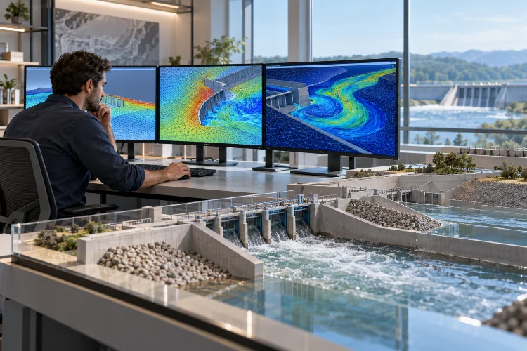
Instead of simulating individual hydraulic components in isolation, coupled modeling connects multiple numerical systems to represent how water moves between them.
Engineers can investigate surface flooding, underground drainage, river discharge, and infrastructure operations within a coordinated simulation.
This approach is becoming increasingly valuable as cities expand, extreme rainfall creates new engineering challenges, and aging infrastructure requires smarter upgrades.
But how exactly do these integrated simulations work? And what makes them more useful than traditional hydraulic modeling methods?
Let’s explore the technology, engineering principles, practical applications, and strategies behind reliable coupled hydraulic simulations.
1. Why Modern Water Infrastructure Needs Coupled Hydraulic Modeling
Water infrastructure is a network of interconnected systems. A river may receive stormwater from urban drains, a detention basin may discharge through a controlled outlet, and a pumping station may depend on downstream water levels.
When engineers study these components separately, they can overlook interactions that significantly influence system performance.
For example, imagine a stormwater drainage pipe designed to carry runoff toward a nearby river. Under normal conditions, the pipe discharges efficiently because the river’s water level remains relatively low.
During a flood, however, the downstream river level rises. This creates backwater pressure that can reduce drainage capacity and potentially cause water to accumulate inside the network.
A standalone drainage simulation with an unrealistic fixed downstream boundary might underestimate this risk.
The Limitations of Traditional Modeling
Conventional hydraulic models generally focus on specific physical processes or infrastructure components.
One model may calculate flow through underground pipes, while another simulates flooding across the land surface. A separate system might estimate river discharge or reservoir storage.
Each can provide valuable results, but problems arise when interactions between these systems are ignored.
Coupled modeling connects the relevant calculations so information can pass between model components.
Instead of treating upstream runoff, sewer capacity, river levels, and surface inundation as entirely seperate problems, engineers can evaluate how they influence one another.
The result is a more realistic representation of complicated water infrastructure behavior, provided the model connections and underlying assumptions are properly configured.
2. Understanding How Different Hydraulic Models Work Together
Coupled hydraulic modeling isn’t a single simulation technique. It’s a general approach that links different mathematical representations of water movement.
Some applications combine one-dimensional and two-dimensional hydraulic models. Others integrate rainfall-runoff calculations, groundwater processes, operational controls, or localized three-dimensional simulations.
The appropriate combination depends on the engineering problem.
Combining 1D and 2D Hydraulic Simulations
One-dimensional models are especially useful for representing water movement through pipes, channels, and river reaches.
They generally calculate quantities such as discharge, water level, and hydraulic head along defined network elements.
Two-dimensional models describe how water moves across a horizontal surface. They can estimate flood depth, flow direction, and velocity over streets, floodplains, and other terrain.
Connecting these two approaches creates a practical way to simulate underground drainage and surface flooding together.
For instance, when a sewer network becomes overloaded, water may escape through manholes and spread across nearby roads.
A coupled 1D–2D model can calculate this exchange and track the resulting overland flow.
The interaction may also work in reverse. Surface water can enter drainage inlets when there is available capacity within the network.
Linking Hydrology and Hydraulics
Hydrological models describe how rainfall becomes runoff, while hydraulic models calculate how that water moves through channels, pipes, structures, and floodplains.
When connected, these models can represent the progression from rainfall to downstream flooding.
Consider a watershed experiencing intense precipitation.
A rainfall-runoff component estimates the timing and volume of runoff generated across different areas. That information is then transferred into a hydraulic model to calculate water levels, velocities, and possible inundation.
The U.S. Environmental Protection Agency’s Storm Water Management Model (SWMM) provides capabilities for simulating rainfall-runoff processes and flow routing through urban drainage networks.
Including Groundwater Interactions
Some infrastructure projects also require groundwater modeling.
For example, a river may gain water from an aquifer during dry periods or lose water to surrounding sediments under different hydraulic conditions.
The U.S. Geological Survey’s GSFLOW framework integrates surface-water and groundwater simulation processes to investigate these interactions.
Such approaches can be useful for assessing groundwater withdrawals, managed recharge, and long-term watershed behavior.
However, groundwater coupling isn’t necessary for every hydraulic project. It becomes valuable when subsurface exchanges materially affect the decisions being studied.
3. Essential Data for Building Accurate Coupled Models
A sophisticated simulation still depends on reliable input information.
If river elevations are inaccurate, drainage connections are missing, or pump capacities are incorrectly specified, the model may produce misleading results.
That’s why building the dataset is often just as important as selecting the numerical solver.
Terrain, Infrastructure Geometry, and Network Connectivity
Digital Elevation Models provide information about the ground surface, helping numerical software represent drainage pathways and flood-prone areas.
High-resolution terrain surveys can identify road embankments, depressions, levees, and other obstacles that redirect surface water.
Underground infrastructure requires additional information.
Engineers need pipe diameters, lengths, slopes, invert elevations, manhole locations, and hydraulic structure dimensions.
Even relatively small elevation errors can influence how water moves through low-gradient drainage networks.
For example, an incorrectly positioned culvert invert may affect the calculated upstream water level and the timing of overflow.
Accurate network connectivity is equally important. A missing pipe connection can unintentionally isolate part of the system.
Rainfall, Flow Records, and Operational Information
Hydrological observations provide the driving conditions for many coupled simulations.
Rainfall records help describe storm intensity and duration, while river gauges provide information about water levels and discharge.
Pump operating curves, valve settings, reservoir levels, and gate-control rules may also be necessary.
Imagine a detention basin that releases water through an automated outlet.
If the operational rules aren’t represented correctly, the simulation may predict unrealistic storage levels or discharge patterns.
Reliable modeling therefore requires both physical infrastructure data and an understanding of how the system is operated.
Defining the Exchange Points
Coupling locations determine where water moves between model components.
These connections might represent manholes, stormwater inlets, riverbanks, culverts, weirs, or pumping facilities.
For example, the MIKE+ modeling environment supports different 1D–2D connections between drainage networks, river systems, and overland flow domains.
Each exchange point needs appropriate geometric and hydraulic characteristics.
Getting these interfaces right is essential because even a small connection error can influence flooding predictions across a much larger area.
4. Numerical Coupling Methods and Simulation Stability
Connecting multiple hydraulic models involves more than exchanging datasets.
The numerical solvers must communicate in a way that preserves physically meaningful flow behavior and avoids unstable calculations.
This introduces several technical considerations that engineers need to understand.
One-Way Versus Two-Way Coupling
In one-way coupling, information moves from one model to another without returning feedback during that exchange.
A common example involves using a rainfall-runoff model to generate an inflow hydrograph for a downstream hydraulic simulation.
This approach is relatively straightforward and computationally efficient.
However, one-way coupling can be insufficient when feedback significantly affects the original system.
Two-way coupling allows models to exchange information in both directions.
For example, a drainage model transfers overflowing water to a surface flood model. The calculated surface water depth can then influence how much water re-enters the drainage network.
This interaction helps represent changing hydraulic conditions more realistically.
Conservation of Mass and Numerical Synchronization
One important principle in coupled simulation is conservation of mass.
If one model transfers a certain volume of water to another, the receiving model should account for the corresponding volume, subject to the numerical formulation and any separately modeled sources or losses.
Otherwise, artificial gains or losses may appear.
Engineers also need to consider time synchronization.
A detailed surface flow model might require short calculation intervals, while another model component could operate using longer time steps.
The coupling framework must manage these differences carefully.
Some systems exchange information at fixed synchronization intervals. Others use iterative procedures to improve agreement between connected solutions.
The U.S. Army Corps of Engineers’ HEC-RAS documentation describes numerical tolerances and iteration options for 1D-2D hydraulic connections.
Balancing Accuracy and Computational Efficiency
Smaller computational cells can improve the representation of complex geometry, but they also increase processing requirements.
Consider a one-square-kilometer floodplain.
A uniform grid with 10-meter cells contains approximately 10,000 cells. Reducing the resolution to five-meter cells increases the total to around 40,000 cells.
That’s four times the number of cells for the same area.
Additional time-step restrictions may further increase simulation costs.
A practical strategy involves refining the mesh around critical hydraulic structures while maintaining coarser resolution elsewhere.
This helps engineers obtain useful detail without unnecessarily increasing computation time.
5. Practical Applications in Complex Water Infrastructure Design
The real advantage of coupled simulations becomes clear when engineers apply them to infrastructure planning.
Integrated models allow project teams to investigate multiple hydraulic processes under a shared set of operating conditions.
This can reveal design weaknesses that would otherwise remain difficult to detect.
Urban Drainage and Flood Prevention
Urban drainage is one of the strongest use cases for 1D-2D modeling.
Imagine a city district covering two square kilometers and receiving 40 millimeters of rainfall during a storm.
The total precipitation volume over that area would be approximately 80,000 cubic meters.
Not all of that water becomes runoff, of course. Some infiltrates into the ground, evaporates, or remains in temporary storage.
However, heavily developed areas with extensive impervious surfaces can generate substantial runoff volumes.
A coupled simulation can estimate how runoff enters drainage pipes, where network capacity becomes insufficient, and how excess water spreads across streets.
Engineers can then compare improvements such as larger culverts, additional storage facilities, or redesigned drainage routes.
Reservoirs, Dams, and Flood-Control Structures
Coupled simulations can also support water-control infrastructure design.
Reservoir operation influences downstream discharge, while downstream hydraulic conditions may affect the performance of certain outlet structures.
Engineers can connect storage calculations, operational rules, and downstream hydraulic models to evaluate different release strategies.
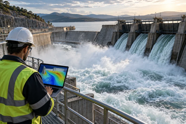
For example, a simulation might compare how alternative gate operations influence downstream flood levels during a major inflow event.
These scenarios can help identify operational constraints and potential infrastructure upgrades.
Coastal Drainage and Pumping Stations
Coastal cities face particularly complicated drainage conditions.
Heavy rainfall may occur while high tides prevent stormwater from discharging freely into the sea.
A coupled model can represent interactions between stormwater networks, surface flooding, and changing coastal water levels.
Engineers can investigate whether additional pumps, tide gates, or retention storage would improve drainage performance.
The same approach helps evaluate how sea-level changes may affect future infrastructure capacity.
Water Distribution and Operational Planning
Pressurized water supply systems introduce another class of hydraulic challenges.
Engineers may need to understand pipe pressure, pump energy use, tank storage, and changing consumer demand.
EPA’s EPANET software provides extended-period hydraulic simulation capabilities for pressurized water distribution networks.
These results can inform integrated operational studies involving treatment facilities, storage reservoirs, and pumping infrastructure.
However, connecting pressurized distribution models with other hydraulic systems generally requires appropriate boundary exchanges or a specialized integration framework.
The underlying engineering principle remains the same: connected infrastructure decisions benefit from evaluating important system interactions.
6. Calibration, Validation, and Managing Model Uncertainty
A coupled model can contain millions of calculations and still produce inaccurate predictions.
Numerical complexity doesn’t automatically guarantee reliability.
Engineers need to demonstrate that simulated behavior reasonably matches physical observations.
Calibrating Individual and Connected Components
Calibration involves adjusting uncertain parameters within physically defensible ranges.
For drainage systems, these might include pipe roughness, runoff characteristics, or inlet efficiency.
River models may require refinement of channel resistance and hydraulic structure parameters.
When possible, individual model components should be evaluated before connecting them into a larger system.
This helps isolate errors and makes troubleshooting much easier.
Once the components perform satisfactorily, engineers can examine how the connected system responds to observed events.
For example, they might compare simulated water levels against river gauge records while also checking observed flooding around drainage manholes.
This provides a more comprehensive picture of model performance.
Validating Against Independent Observations
Validation examines model performance using observations that were not used for parameter calbration.
Useful measurements include water-surface elevations, flow rates, pump records, flood depths, and mapped inundation boundaries.
Statistical indicators can support the evaluation.
Root Mean Square Error (RMSE), for instance, summarizes differences between simulated and observed numerical values.
Flood extent comparisons can also reveal whether the model predicts inundation in the correct locations.
No single metric provides a complete assessment, so combining several performance measures is generally preferable.
Exploring Uncertainty With Scenario Analysis
Uncertainty is unavoidable in hydraulic engineering.
Rainfall estimates, terrain measurements, roughness coefficients, and infrastructure operating conditions may all contain errors.
Instead of relying on a single assumed scenario, engineers can perform sensitivity tests.
For example, they might evaluate several rainfall intensities, alternative pump failures, or different downstream river levels.
If relatively small input changes produce major differences in predicted flooding, the design may require additional investigation.
This approach helps decision-makers understand the range of possible outcomes rather than treating one model result as a guaranteed prediction.
7. Choosing Modeling Software and Building a Smarter Workflow
Selecting the right software is important, but no single platform is ideal for every project.
A small drainage upgrade may need a relatively straightforward network model. A regional flood management study may require integrated river, drainage, and floodplain simulations.
The best approach depends on the physical processes, available information, and desired engineering outputs.
Common Tools for Integrated Hydraulic Analysis
Several established platforms support different parts of coupled hydraulic modeling.
HEC-RAS supports one-dimensional and two-dimensional river hydraulics, including connections between river reaches, floodplains, and hydraulic structures.
MIKE+ offers integrated modeling capabilities involving urban drainage, river networks, overland flooding, and related water infrastructure.
EPA SWMM is widely used for stormwater runoff and drainage network analysis, while EPANET focuses on pressurized water distribution systems.
GSFLOW provides a framework for investigations requiring coupled groundwater and surface-water processes.
These tools serve different purposes, and not every model combination can communicate automatically.
Engineers should verify the available coupling interfaces, required licenses, supported numerical features, and compatibility with project data before choosing a platform.
A Practical Step-by-Step Modeling Strategy
An efficient project begins by defining the engineering questions.
Rather than immediately constructing a massive integrated model, determine which interactions actually influence the intended decision.
Next, collect the necessary terrain, rainfall, network, and operational data.
Develop the individual hydraulic components and test their basic behavior before introducing coupling interfaces.
After connecting the relevant systems, check whether exchanged flow volumes, water levels, and boundary conditions behave consistently.
Run initial simulations using manageable scenarios before progressing to extreme events or detailed alternatives.
Finally, perform calibration, validation, sensitivity analysis, and independent engineering review.
This structured approach improves modeling effeciency while reducing the likelihood of hidden errors.
The objective isn’t to create the most complicated simulation possible. It’s to develop a dependable decision-support tool that answers practical infrastructure questions.
Coupled hydraulic modeling offers a more complete way to understand how interconnected water infrastructure behaves under changing conditions.
By linking drainage networks, rivers, floodplains, groundwater processes, and operational systems where appropriate, engineers can identify hydraulic interactions that isolated models may miss.
The benefits extend across urban flood management, pumping station design, reservoir operations, and infrastructure resilience planning.
However, reliable results still depend on accurate input data, carefully defined coupling interfaces, numerical stability, and thorough validation.
As computational technology continues improving, integrated modeling will become an increasingly valuable part of modern water engineering.
Ready to design smarter water infrastructure? Start by identifying the connections between your existing hydraulic systems, reviewing available data, and exploring how coupled simulations can support safer, more efficient, and more resilient engineering decisions.