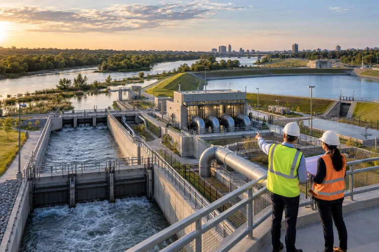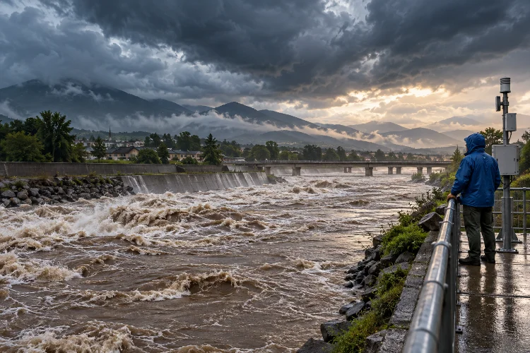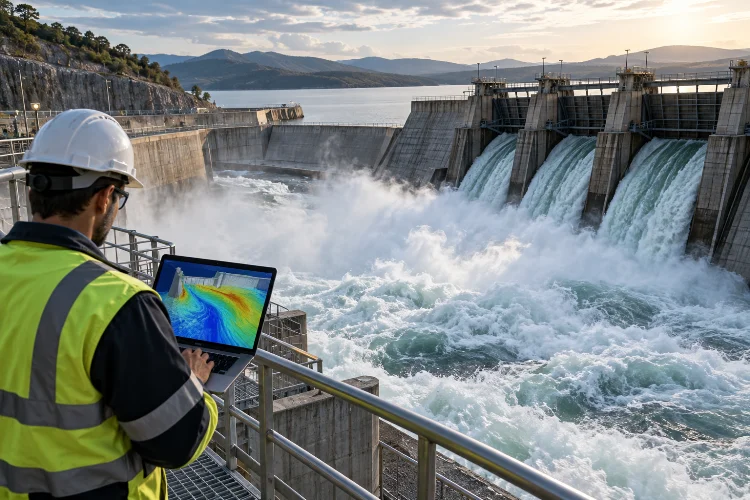
Picture this: your engineering team has spent days preparing a Computational Fluid Dynamics (CFD) simulation of a massive flood-control structure. The geometry looks perfect, the solver is ready, and the computational mesh contains millions of cells.
Then something frustrating happens.
The simulation runs painfully slowly, memory consumption keeps increasing, and the results still show questionable flow patterns around critical structures.
Sound familiar?
In large hydraulic engineering projects, creating a finer mesh doesn’t automatically guarantee better results. What really matters is distributing computational resolution intelligently across the simulation domain.
That’s where mesh optimization techniques for large-scale hydraulic CFD studies become incredibly valuable.
By refining important flow regions, improving cell quality, and reducing unnecessary calculations, engineers can achieve more dependable predictions without overwhelming their computing infrastructure.
Whether you’re modeling river hydraulics, spillways, pumping stations, or complex water distribution systems, choosing the right meshing strategy can make a significant difference.
In this guide, we’ll explore practical mesh optimization methods, common challenges, and proven approaches for improving simulation accuracy while keeping computational costs under control.
1. Understanding Mesh Optimization in Large-Scale Hydraulic CFD
Before exploring advanced techniques, it’s important to understand what mesh optimization actually means.
In CFD, the computational mesh divides a fluid domain into smaller elements or cells. Numerical solvers use these cells to calculate variables such as velocity, pressure, turbulence, and fluid movement.
The quality and distribution of these elements influence how accurately the simulation represents physical flow behavior.
Why Mesh Resolution Matters
Imagine simulating water flowing through a large hydroelectric dam.
Some areas, such as the upstream reservoir, may experience relatively gradual changes in velocity. Other regions, including spillway gates and energy dissipation structures, can contain rapidly changing flow patterns.
Using the same fine mesh throughout both regions wastes computational resources.
Instead, mesh optimization focuses computational detail on areas where fluid behavior is more complicated.
This strategy allows engineers to investigate turbulence, pressure gradients, flow separation, and hydraulic losses without unnecessarily increasing the size of the entire numerical model.
The Hidden Cost of Excessive Mesh Density
There’s a common misconception that doubling mesh resolution simply doubles computational effort.
In three-dimensional simulations, the situation is more complicated.
If the cell dimensions are reduced by half in every spatial direction, a region containing one million uniform cubic cells could require approximately eight million cells.
Transient simulations may also need smaller time steps to maintain acceptable numerical behavior.
Consequently, simulation time and memory requirements can increase dramatically.
The objective isn’t to create the largest possible mesh. It’s to create the smallest mesh that delivers sufficiently accurate results for the engineering question.
That distinction forms the foundation of efficient hydraulic CFD modeling.
2. Choosing the Right Mesh Structure for Hydraulic Simulations
One of the earliest optimization decisions involves selecting an appropriate mesh structure.
Different cell arrangements offer different advantages, particularly when hydraulic geometries become complicated.
Structured vs. Unstructured Meshes
Structured meshes use an organized arrangement of cells, commonly quadrilateral elements in two dimensions or hexahedral elements in three dimensions.
Their regular connectivity can support efficient numerical calculations, especially in relatively straightforward geometries.
For example, a long rectangular channel may be well suited to a structured mesh because its geometry follows predictable directions.
Unstructured meshes offer greater flexibility.
They can accommodate irregular riverbeds, complicated intake structures, curved pipelines, and other geometries that would be difficult to represent with a simple structured grid.
However, flexibility sometimes comes with additional computational and memory overhead, depending on the chosen element types and solver.
Why Hybrid Meshes Are Often Practical
Hybrid meshes combine different cell types to balance geometric flexibility and numerical performance.
A hydraulic simulation might use hexahedral cells in relatively regular regions, with other polyhedral or tetrahedral elements around complex structural details.
Prismatic cells can also be introduced near walls to capture important velocity gradients.
The best arrangement depends on the geometry, turbulence treatment, and available CFD software.
OpenFOAM’s snappyHexMesh, for example, supports automatic mesh refinement, surface fitting, and optional prism-layer generation.
This makes it useful for complicated three-dimensional engineering domains where manually constructing every element would be impractical.
Before choosing a mesh type, engineers should consider how well it represents the geometry and supports the desired flow physics.
3. Using Local Mesh Refinement to Improve Simulation Accuracy
Local mesh refinement is among the most effective ways to optimize large hydraulic CFD studies.
The concept is simple: increase resolution where important flow features occur and reduce it where conditions are relatively uniform.
This sounds straightforward, but knowing exactly where to refine requires engineering judgment.
Identify Critical Hydraulic Regions
Consider a bridge crossing a river.
Water accelerates around bridge piers, separates behind structural surfaces, and develops complex downstream wakes.
These regions often require significantly more spatial detail than sections of the river located far from the structure.
Similarly, in spillway simulations, important refinement locations may include gate openings, spillway crests, hydraulic jumps, and energy dissipation basins.
Engineers can create localized refinement zones surrounding these features.
The surrounding domain remains comparatively coarse, reducing the total number of computational cells.
For example, a hypothetical model requiring eight million cells under a uniformly fine-grid strategy might need substantially fewer cells with selective refinement.
The actual savings depend on how much of the domain needs detailed resolution.
Apply Gradual Mesh Transitions
Abrupt changes between large and small cells can introduce numerical difficulties.
Large differences in neighboring cell dimensions may affect discretization accuracy, interpolation, and overall solution quality.
A better approach uses gradual mesh transitions.
Buffer zones allow cell sizes to increase progressively as the mesh moves away from critical hydraulic features.
OpenFOAM’s refinement controls support this concept by allowing users to define refinement levels around surfaces, geometric features, and selected volumes.
Refine Near-Wall Flow Regions
Walls and solid boundaries deserve special attention.
Water moving close to a channel wall, pipe surface, or hydraulic structure experiences velocity gradients that influence wall shear stress and energy losses.
Boundary-layer meshing introduces carefully arranged cells near these surfaces.
Engineers often evaluate the dimensionless wall distance, known as y+, to determine whether the mesh is suitable for the selected turbulence model and near-wall treatment.
There isn’t one universal y+ target for every CFD simulation.
Appropriate values depend on whether the model resolves the near-wall region directly or uses wall-function approximations.
4. Applying Adaptive Mesh Refinement for Complex Flow Conditions
Traditional mesh refinement relies heavily on predicting important flow regions before running a simulation.
But hydraulic conditions can change dramatically over time.
Consider a flood wave moving through a narrow channel or a hydraulic jump shifting downstream.
A refinement strategy based only on fixed geometric locations may miss important evolving flow structures.
This is where adaptive mesh refinement becomes useful.
How Adaptive Mesh Refinement Works
Adaptive Mesh Refinement (AMR) modifies computational resolution according to selected criteria.
A simulation may begin with a relatively coarse mesh and identify regions requiring additional detail.
The software can then refine cells around strong velocity gradients, high vorticity, pressure changes, or moving fluid interfaces.
Depending on the solver and adaptation method, cells in less demanding regions may also be coarsened.
Ansys Fluent, for instance, provides solution-adaptive mesh refinement and coarsening based on geometric information and numerical solution fields.
This can reduce unnecessary computational effort compared with maintaining maximum resolution everywhere.
Adaptive Meshing for Free-Surface Flows
Free-surface hydraulics presents particularly interesting challenges.
In applications involving flood waves, spillways, and water – air interactions, the water surface may move considerably throughout the simulation.
Volume of Fluid (VOF) methods represent the distribution of fluid phases and can be combined with suitable adaptive refinement techniques.
For example, additional cells may be introduced near a moving water – air interface to improve interface resolution.
However, adaptation isn’t free.
Repeatedly refining cells, transferring solution variables, and balancing computational workloads introduce additional processing costs.
Poorly configured adaptation can also create numerical disturbances or excessive cell counts.
The most effective strategy is to refine only when the expected improvement justifies the added computational effort.
5. Improving Mesh Quality and Numerical Stability
A large number of cells means very little if those cells have poor geometric quality.
Even carefully refined meshes can produce unreliable calculations when their elements become excessively distorted.
That’s why mesh quality assessment should be part of every hydraulic CFD workflow.
Monitor Skewness and Non-Orthogonality
Two important mesh-quality indicators are skewness and non-orthogonality.
Skewness describes how much a cell or face deviates from an idealized shape, while non-orthogonality measures geometric misalignment between cell-center connections and face normals.
High values can complicate numerical calculations, particularly when estimating gradients and fluxes across cell faces.
OpenFOAM provides mesh-quality controls for these characteristics, along with other parameters such as cell volume and geometric distortion.
The acceptable thresholds depend on the solver, numerical scheme, and mesh topology.
Instead of relying entirely on default values, engineers should examine problematic cells and determine whether local geometry changes or remeshing would improve the model.
Balance Cell Shape and Aspect Ratio
Aspect ratio describes the relationship between a cell’s characteristic dimensions.
Highly stretched cells aren’t necessarily bad.
For example, boundary-layer elements are intentionally elongated parallel to walls to resolve steep gradients in the wall-normal direction.
Problems arise when cells are stretched in unsuitable directions or combined with poor alignment and distorted geometry.
The objective is to make cell orientation consistent with the local flow physics and numerical method.
Connect Mesh Resolution With Time-Step Selection
Mesh optimization also affects transient simulation settings.
Smaller cells may require smaller time steps, particularly when using explicit algorithms or enforcing Courant-number limits.
The Courant number relates the distance fluid travels during a time step to the characteristic computational cell size.
Its acceptable value depends on the solver and discretization method.
Therefore, reducing cell dimensions without reviewing time-step settings can create stability problems or considerably increase computation time.
Mesh design and temporal resolution should be optimized together rather than treated as completely seperate tasks.
6. Conducting Mesh Independence and Grid Convergence Studies
How do you know when a mesh is sufficiently refined?
That’s one of the most important questions in computational hydraulics.
A simulation may produce smooth contours and realistic-looking animations, but visual quality doesn’t guarantee numerical accuracy.
Mesh independence studies help determine whether further refinement meaningfully changes the predicted results.
Compare Coarse, Medium, and Fine Meshes
A practical approach involves running several simulations with progressively finer grids.
Consider a hypothetical hydraulic structure where the main output is total pressure loss.
Suppose three meshes produce the following results:
| Mesh Level | Cell Count | Pressure Loss |
|---|---|---|
| Coarse | 450,000 | 24.8 kPa |
| Medium | 1,100,000 | 24.1 kPa |
| Fine | 2,700,000 | 23.9 kPa |
These illustrative results suggest that the predicted pressure loss is becoming less sensitive to refinement.
The difference between the medium and fine results is approximately 0.83% relative to the medium-grid prediction.
However, this comparison alone doesn’t establish numerical independence or physical accuracy.
Engineers must also examine solver convergence, consistent boundary conditions, refinement ratios, and possible uncertainties.
Use the Grid Convergence Index
NASA’s CFD verification guidance describes methods for evaluating spatial discretization error, including Richardson extrapolation and the Grid Convergence Index (GCI).
GCI provides a systematic way to estimate uncertainty associated with numerical grid resolution.
A properly conducted study generally benefits from three or more systematically refined meshes.
It’s particularly useful when engineering decisions depend on small differences between competing designs.
For example, if two spillway alternatives produce nearly identical predicted pressure loads, understanding numerical uncertainty helps determine whether that difference is meaningful.
Validate Results Against Physical Evidence
Mesh convergence and model validation are not the same thing.
A solution can converge numerically while still representing the physical system incorrectly.
Boundary conditions, turbulence assumptions, geometric simplifications, and roughness parameters may introduce substantial uncertainty.
Whenever possible, compare simulation outputs with laboratory measurements, field observations, or established hydraulic calculations.
Useful validation quantities include discharge, water-surface elevation, velocity profiles, and pressure distributions.
The purpose of validation is to establish whether the numerical model adequately represents real hydraulic behavior.
7. Scaling Mesh Optimization for Large Hydraulic CFD Projects
Large-scale simulations introduce challenges that smaller CFD studies rarely encounter.
Complex river geometries, extensive computational domains, and long transient simulations can place substantial demands on computing infrastructure.
Fortunately, several strategies can improve effeciency without sacrificing essential hydraulic detail.
Use Domain Decomposition and Parallel Computing
Domain decomposition divides a computational mesh into smaller regions that can be processed by multiple CPU cores.
This allows large simulations to run across multicore workstations or high-performance computing clusters.
However, parallel performance depends on more than processor count.
Poor workload distribution can leave some processors overloaded while others remain underused.
Communication between partitions can also become expensive, particularly when meshes contain many small regions or irregular connections.
Good partitioning attempts to balance computational workloads while limiting unnecessary communication.
When adaptive refinement changes cell distribution, the domain may need to be repartitioned to maintain performance.
Combine Large-Scale and Local Hydraulic Models
Another useful strategy is combining simulations operating at different spatial scales.
For example, a broader one-dimensional or two-dimensional hydraulic model can estimate river water levels and flow distribution.
A smaller three-dimensional CFD model can then examine detailed conditions around a bridge, intake structure, or spillway.
This approach reduces the need to resolve highly detailed three-dimensional flow across an entire watershed.
The US Army Corps of Engineers provides practical guidance on mesh refinement, breaklines, and cell alignment in HEC-RAS two-dimensional hydraulic modeling.
Although HEC-RAS 2D meshing isn’t equivalent to constructing a three-dimensional CFD mesh, the broader principle remains relevant: computational detail should reflect topography, important flow paths, and engineering objectives.
A Practical Example: Optimizing a Spillway Model
Imagine engineers evaluating a large spillway with complex gate openings and a downstream stilling basin.
Their first model uses a relatively coarse three-dimensional mesh to understand general flow patterns.
Initial results reveal strong velocity gradients near the gate openings and intense circulation inside the stilling basin.
Instead of refining the entire domain uniformly, the engineers increase mesh density in these critical areas.
They also improve near-wall cell arrangements and smooth the transitions between refinement zones.
Next, the team performs additional simulations using progressively finer meshes.
Pressure distributions, discharge predictions, and energy dissipation estimates are compared with available hydraulic measurements.
Finally, the model is partitioned for parallel computing to reduce simulation time.
This workflow allows the team to recieve detailed information about important hydraulic processes while avoiding unnecessary computation elsewhere.
The essential lesson is that mesh optimization works best as an iterative engineering process.
Effective mesh optimization is one of the most valuable ways to improve large-scale hydraulic CFD simulations.
By combining appropriate mesh structures, localized refinement, adaptive methods, and strict quality checks, engineers can achieve detailed flow predictions without creating unnecessarily expensive numerical models.
Mesh independence studies, physical validation, and parallel computing further strengthen the reliability and practicality of these simulations.
More importantly, a well-designed mesh helps engineers understand complicated hydraulic behavior while making better decisions about infrastructure safety, performance, and design.
Ready to improve your next hydraulic CFD project? Start by identifying the flow regions that matter most, evaluate your current mesh quality, and establish a clear grid convergence strategy.
With a thoughtful approach, even complex hydraulic simulations can become more manageable, accurate, and computationally efficient.